|
EPPL
0.1 alpha
|
|
|
EPPL
0.1 alpha
|
|
Parallel input-output ports in embedded systems are one of the most important ways of communication between a software and the external world.
There are two problems with using the microcontroller ports.
The first problem is a device specific one, in some devices it could be more and in some less annoying. To fully support a port pin, in a standard AVR8 family microcontrollers,, we have to take care of 3 registers:
There is no guarantee that these registers are put in any order in a register map. Cursory reading of some avr8 documentations may lead us to notice, that most of them are put one after another. But there are some exceptions that we could not ignore. In ATmega128 microcontroller:
So far so good, but:
If there were not such exceptions, we could define the whole port as a structure:
We could easily access all port registers using structure above.
This kind of access was introduced with the AVR XMEGA family. In old AVR8, we cannot trust it, and we should use specific registers names directly in our code.
There is not a problem with using the port registers direct in code:
But in a real program, we rather do not use port pins numbers or port registers in the code directly. We would try to extract hardware pins definitions from functional code.
In ideal world, there would be everything, that is hardware dependent in one file, and everything that is hardware independent in other file.
So let's try to define some simple system:
In the code above we have to provide information about our ports 3 times. The definition like the one above is quite error-prone, and it is just not nice. It would be much better if we could just inform compiller that we are going to use port C to our button. We know that port C uses registers DDRC, PORTC and PINC.
There is also the second problem with our definitions. We have to provide 7 bits in one port for our LCD. It is not always possible. Sometimes we will have just 3 pins available in one, 2 available in other and 2 in other one port available. To define such a possibility in the way as in the code above, we have to use 4 lines to define every single pin. It begins to be really messy.
In August of 2005, I presented simple solution for the first described problem. The solution was presented in "Electronics for Everybody" Polish magazine.
These were just 6 simple macros (out of which 3 for usage and 3 internals):
It is an extremely simple code, that works just by preprocessor possibilities. Using these macros makes hardware definitions much easier and more elegant. And most important of all: using these macros do not have any disadvantages! It does not slow down (noticeably) the compilation time. And most important of all: it does not generate any more machine code than needed.
Using these macros, we can define our hardware in the following way:
And now how we access our ports registers:
So one problem could be solved simply. But this is just a simple and machine dependent problem. We have to process it once again if we change machine type.
Producers are trying to make it simpler for us. In new Cortex-M3 concept we would get libraries from producer, that would help us with ports usage. They are not always optimal, but help a lot.
But there is another, more general problem described in the next section...
Second problem is a general problem.
In a typical microcontroller we use some pins not only as a part of General Input Output Ports. Some of pins have special functionality, e.g. USART port, PWM outputs, Interrupt input... That makes pins selection not fully independent. We have to consider the hardware limitations of our microcontroller.
It is rather a problem in middle scale systems. In relatively small systems we do not have many different elements connected to ports. So in this situation pins selection is quite simple.
On the other hand, in relatively big systems, we usually have a microcontroller that is big enough to think about pins in port groups. We can have separated port for buttons, separated for display driver and so on...
But in middle scale systems, we often have a situation that we lack pins for general usage. We have enough pins for all our peripherals, but some of them have special hardware functionality and we have to use them.
As a result, when we need to drive an LCD, we could find out that we have even more free pins that we need, but they are distributed between ports.
And last but not least - what about code recycling? We are often creating some code blocks, some libraries, that we would like to reuse in next design. In one project we could afford to give our LCD library full port. But maybe in another project we would have to split LCD connections.
Wouldn't it be great to have a library that would take care of it? Wouldn't it be great if this library would generate quite optimal code? And in the end of the day... wouldn't it be great, if your newly created code, that uses an I/O ports a lot, could be easily moved to an extremely different machine? Let's say, your newly created LCD support library, written for AVR8, could be moved to ARM7 without extreme recoding?
As for me - It all would be great and these are the reasons for the creation of this library.
If you are still not convinced, read these section to the end...
Take a look at the first image:
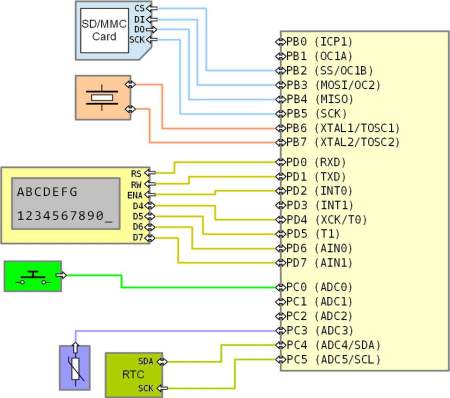
What we have here are some basic microprocessor system. This is a synthetic (not a real) design. It uses an ATmega8 microcontroller. Let's say it is some temperature logger with an alphanumeric LCD, real time clock, simple keyboard, and SD card.
On the image above we are able to divide functionality simply into ports.
It is a simple and logical system. We are able to divide all functionality by using codes analogous to listings that were presented earlier.
Now imagine that the project is going to be upgraded.
The image below, shows our, modified design:
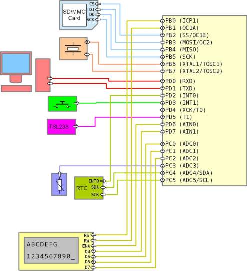
I would like you to focus on what happens with our LCD connections. We do not even have 4 free pins together on one port. If we had it, we could divide our LCD support logically to data and control ports. But now we have it totally distributed between the ports and there is not any logic in that.
If you write your library bearing in mind that LCD is connected to one port, after project upgrade, you have to totally rebuild it.
I used to have more or less similar problems, so I decided to create this library. It makes it possible to write a program totally independent from pins mapping. If you map your pins simply to one port, generated code would be short and fast. If you map pins in a totally random way, generated code will be a little bit more complicated - but it will still work!
One of the first thing we have to do when our program starts is to initialize input-output ports. Basically, there are two ways to do it (or some modifications and/or combinations of these two methods):
Before continuing, I will put here again the image of our modified system:
Using the conception, described in the section Simple solution to the first problem, we could write our hardware definition file:
Notice, that every single pin has two lines of definition there. One is for the port and the other one is for the pin definition.
We would use this code and the image above in initialization examples in following subsections.
Below is an example of this method of port initialization:
In this example we assumed that all ports registers are initialized with 0. We only have to change the bits in the registers when we would like them to be set.
In most cases it is true that we have 0 in all port register bits before initialization. But it could be risky assumption and it could make our code refactoring harder in the future.
Moreover - notice that it is still not a complete code. It leaks in a card pins initialization. But even this part of initialization would generate 13 sbi instructions. And if some registers are outside from a bit addressable region, there have to be 3 instructions generated for every bit set!
Below is an example of this method of port initialization:
I prefer this method. It is harder to read but it is more reliable and shorter in the generated code. In the worst-case scenario, it would generate 12 instructions (ldi and out).
Notice that we have some default configuration defined. All pins that are not initialized would have following settings: DDR=0, PORT=1. It means they would be set to Pull Up inputs.
The EPPL library gives us a possibility to define port configuration pin by pin, much like in the first solution. But it would automagically convert it to simple direct writing bytes to the right registers just like in the second solution.
In the EPPL library we would define our hardware configuration like below:
Then we can use this hardware declaration to initialize our pins:
Now the code refactoring is extremely simple. Generated code is optimal.
Notice how the EPPL library makes it simple to define our hardware configuration - we are using one line for a pin. This one line already contains information about port letter and pin number in the port. This way of port definition is more "human friendly" than the method where we used two lines for every pin.
 1.8.3.1
